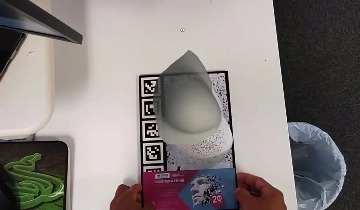
Getting a breast tissue model out of the solver and onto a silicone phantom on a desk, seen through a HoloLens 2, and making it stay there.
The breast group at the Auckland Bioengineering Institute works on a problem that sounds simple and is not. Breast tissue is soft, and soft things move. A tumour that a radiologist locates in a prone MRI scan is somewhere else entirely by the time the patient is lying supine on an operating table, or standing up, or compressed flat in a mammography machine. Gravity alone can shift things by centimetres.
So the group builds finite-element models: mesh the tissue, give it constitutive properties, apply a gravity load, and solve for where everything ends up. The output is a deformed geometry that says "under these conditions, this is the shape."
Then comes the awkward part. How do you know the model is right?
The gap between a plot and a thing
The usual answer is to compare the simulated surface against a scan of the real one, get an error metric, and put it in a paper. That works, but it is a number. It does not tell you where the model is wrong in a way your hands understand, and it is very hard to show a surgeon.
The group had a silicone breast phantom, a physical object with known material properties, speckled with a black-and-white pattern for optical surface reconstruction. The models were validated against it. But the model lived on a monitor and the phantom lived on a bench, and nobody could look at both at once.
That was the brief I picked up: put the model on the phantom. Not a side-by-side render, but the actual solved geometry sitting in the same cubic centimetres of air as the silicone, so you could walk around it and see the disagreement directly.
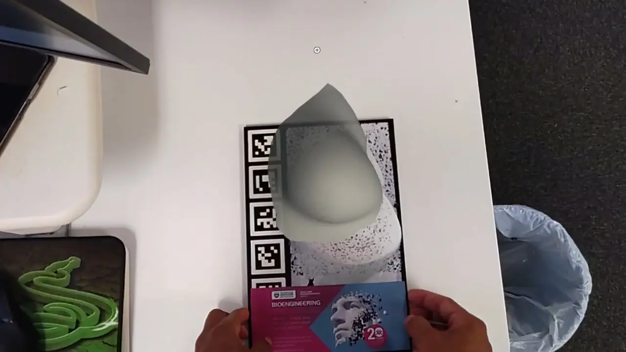
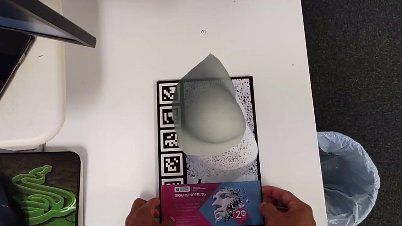 The solved model sitting on the silicone phantom, seen through the headset.
Anchoring
A HoloLens 2 has no idea where your desk is. It builds its own map of the room and it is genuinely good at holding a hologram in place once you have told it where "in place" is. The hard part is that first act of telling.
I used printed fiducial markers. The phantom sits on a card with a column of QR-style markers running down one edge, and the headset reads them to recover the card's position and orientation in its own coordinate frame. From there it is a fixed transform to the phantom, because the phantom always sits in the same spot on the card.
The important decision was what to do after detection. The obvious approach is to keep tracking the marker every frame and keep re-parenting the hologram to it. This is a mistake. Marker pose estimates jitter, especially at the shallow viewing angles you get when you lean over a desk, and the hologram ends up shivering by a few millimetres. On a model whose entire purpose is submillimetre comparison, that is fatal.
So: detect the marker, compute the pose, drop a spatial anchor, then stop looking. After that the headset's own SLAM holds the hologram, and it is rock solid. You can walk to the other side of the office and the model is still exactly where you left it.
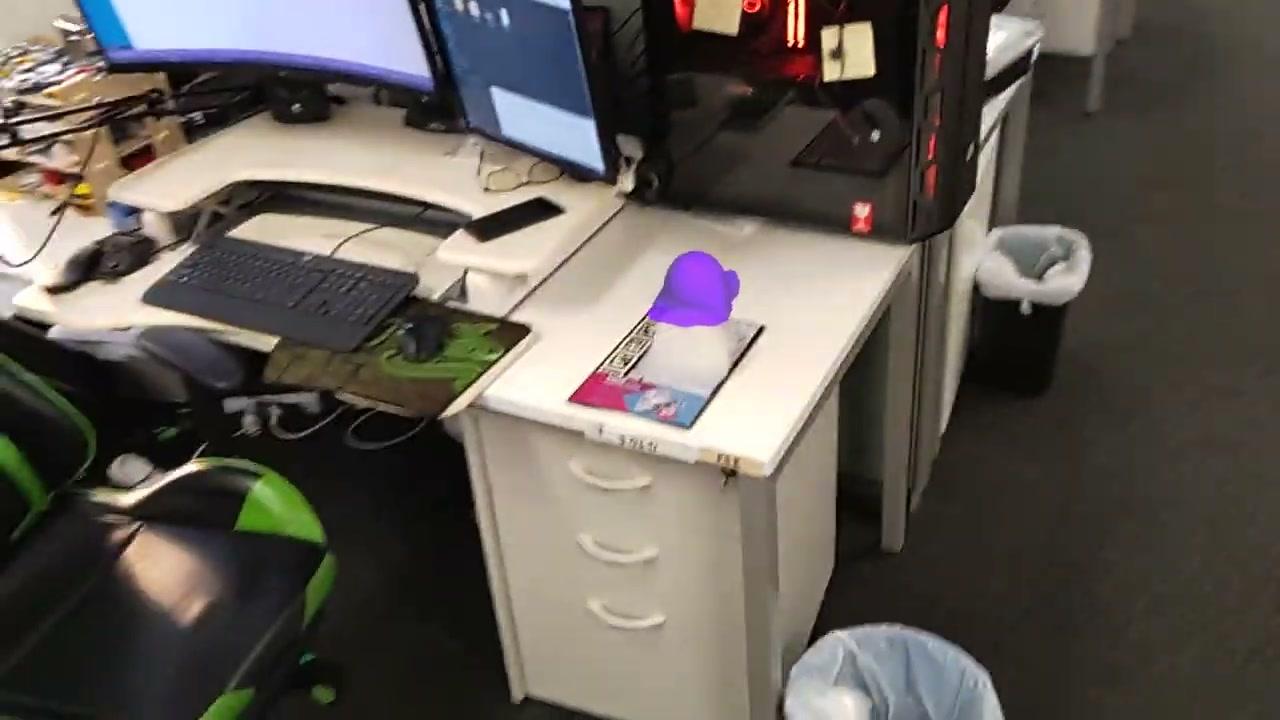 The hologram from across the room, still sitting where it was anchored.
The cost of this approach is that if you move the phantom, the hologram does not follow. That turned out to be fine, and arguably correct: you want the model to stay put so it is obvious when the physical object has been disturbed.
 The marker card. The column of fiducials down the left edge is what the headset reads.
Opacity is the whole feature
Here is the thing that seems trivial and is not. A fully opaque hologram is useless for this task, because it hides the exact object you are trying to compare it against. You need to be able to dial the model down until you can see silicone through mesh.
I built the scene on MRTK with a floating slider panel: red, green and blue channels, plus alpha. Grab the panel to move the whole scene. In practice you end up settling on a translucent tint that contrasts with the phantom, which is why so much of the video is spent in purple.
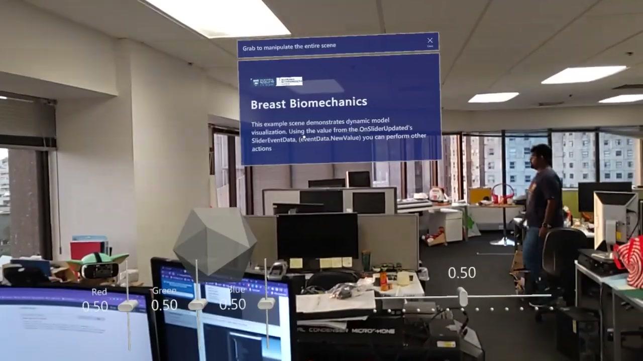 The control panel. Boring to build, and the part people actually used.
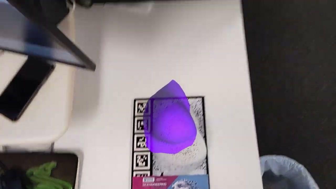 Purple against a white phantom: the tint that made the boundary easiest to read.
The additive display makes this stranger than it sounds. A HoloLens adds light to the world, it cannot subtract it. There is no such thing as a black hologram, and there is no such thing as a genuinely opaque one either. Transparency is free and solidity is impossible. Against a white desk under office lighting, the model washes out badly. Against the darker parts of the room it reads much more clearly. A lot of the tuning was really about finding a colour that survived the ambient light in that particular corner of the building.
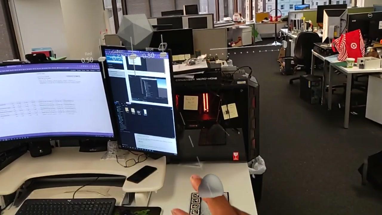 Standing back from the desk. The sliders travel with the scene rather than the head.
What I would do differently
The registration was good enough to be useful and not good enough to be a measurement. Getting from "you can see the discrepancy" to "you can quantify the discrepancy" needs a better anchoring story than a printed card: probably a calibration routine where you touch known points on the phantom and solve for the transform, rather than trusting a fixed offset from a marker.
I also underestimated how much of the work would be presentation rather than plumbing. The pipeline from solver output to Unity mesh was a couple of afternoons. The colour, the opacity, the anchor stability, the question of where to put the sliders so they were reachable but not in the way: that was most of the project, and it was the part that decided whether anyone found it useful.
The development documentation, written up with Thiranja Prasad Babarenda Gamage as a guide for students picking this up, lives here. It covers the environment setup and the Unity side from first principles, which is the thing I most wanted to exist when I started.